2010 Mustang Fuse Box Diagram
Years of production: 2006 2007 2008 2009 2010 2011 2012 2013 2014 2015
The brand Volkswagen is a popular name when it comes to cars that are both performance- oriented and impressive looks. When it comes to a four-seater convertible that is equipped with all the features, then Volkswagen EOS was a popular name. This is because of comfort, impressive looks, sporty handling, and superb riding experience. Apart from the core performance-oriented features, it also has some of the innovative ones that are new for this range. One of them is the heated leather seats that come with the standard version of this car.
Volkswagen EOS: First Generation
This model from Volkswagen has 1.4 TSI BlueMotion Technology that helps to achieve 121bhp. With this power, you will feel the speed while driving. There are other models also that are upgraded to 158bhp 1.4 TSI engine. Apart from this powerful engine specification EOS is quite reliable and safe through the turns. The responsive steering provides good control and handling at steep bends.
When it comes to fuel economy as well as emission, it is at the mid-level as the diesel option can provide 58.9mpg with a CO2 emission of 125gram/km. It has experienced a refreshing design in 2011. The rear and front styling got the upgrades. The recent model has four-bar chrome with sharp headlights. The quality of materials used in the making of cabins is of optimal quality that provides a different level of satisfaction.
The boot space of 380 litres makes it apt for the convertible fold as after folding you will get 205litres of boot space. When it comes to safety, EOS scored a four-star in the Euro NCAP test. Apart from this it also has airbags for drivers, curtains, and passengers, which deploys in a matter of seconds. This model of VW also has a facelift version which comes with special features. Opting for a compact four sized convertible driving machine with these features was the most sensible decision of the people.

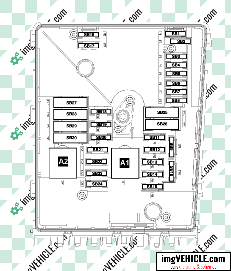
Fuse Arrangements Electronics Box Low, from January 2006
| Number | Amps | Description |
|---|---|---|
| F1 | 20A | Comfort System central control module |
| F2 | 5A | Steering Column Electronic Systems Control Module |
| F3 | 5A | Vehicle Electrical System Control Module |
| F4 | 30A | ABS Control Module |
| F5 | 15A | Direct Shift Gearbox (DSG) Mechatronic |
| F6 | 5A | Instrument Cluster Control Module |
| F7 | 15A | Control module for special purpose vehicles |
| F8 | 15A | Radio/Navigation Display Control Module |
| F9 | 5A | Cell phone operating electronics control module |
| F10 | 5A/10A | Transmission Control Module (TCM) Engine ControlModule (ECM) |
| F11 | 20A | Auxiliary Heater Control Module |
| F12 | 5A | Data Bus On Board Diagnostic Interface |
| F13 | 30A/25A | Engine Control Module (ECM) (only models with diesel engine) Engine Control Module (ECM) (only models with gasoline engine) |
| F14 | 20A | Ignition coil Ignition coil 1 with power output stage Ignition coil 2 with power output stage Ignition coil 3 with power output stage Ignition coil 4 with power output stage |
| F15 | 10A/5A | Heated oxygen sensor (BVY) Oxygen sensor after three way catalytic converter (BVY) Oxygen sensor 2 after catalytic converter (BVY) Oxygen sensor 3 after catalytic converter (BVY) Fuel pump relay Automatic Glow Time Control Module |
| F16 | 30A | ABS Control Module |
| F17 | 15A | High tone horn Low tone horn |
| F18 | 30A | Amplifier |
| F19 | 30A | Wiper Motor Control Module Windshield wiper motor |
| F20 | - | Not used |
| F21 | 15A/10A | Heated oxygen sensor (BMM) |
| F22 | 5A | Clutch position sensor |
| F23 | 5A/10A | Secondary air injection pump relay EGR vacuum regulator solenoid valve Wastegate bypass regulator valve EGR cooler switch-over valve EGR cooler switch-over valve 2 Fuel pressure regulator valve |
| F24 | 10A | Map controlled engine coolingthermostat Coolant fan control module EGR vacuum regulator solenoid valve EVAP canister purge regulator valve 1 Intake manifold tuning valve Camshaft adjustment valve1 Intake manifold runner control valve Ignition coil power output stage |
| F25 | 40a | Vehicle Electrical System Control Module (T11b/1) Terminal 30 - R |
| F26 | 40a | Vehicle Electrical System Control Module (T11c/1) Terminal 30 - L |
| F27 | 50A | Automatic Glow Time Control Module (BMM) |
| F28 | 40A | Power Supply Relay 2 (terminal 15) |
| F29 | - | Not used |
| F30 | 40A | Load Reduction Relay Fuse 7 (on fuse panel C) Fuse 8 (on fuse panel C) Fuse 28 (on fuse panel C) Fuse 35 (on fuse panel C) |

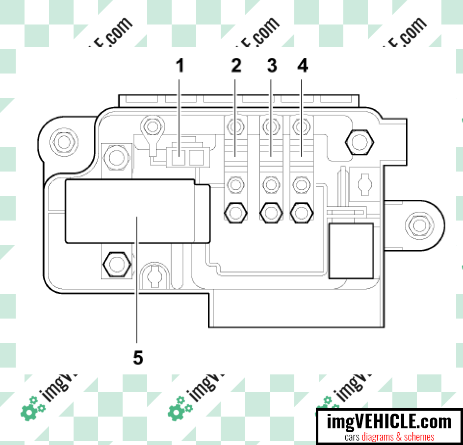
| Number | Amps | Description |
|---|---|---|
| 1 | 125A | Electronics Box Supply Fuse panel A,Relay- and Fuse panel B electronics box |
| 2 | 80A | ElectronicsBox Supply Fuse panel A and Fuse panel B electronics box |
| 3 | 30A | Supply Fuse panel C |
| 4 | 5A | Vehicle Electrical System Control Module |

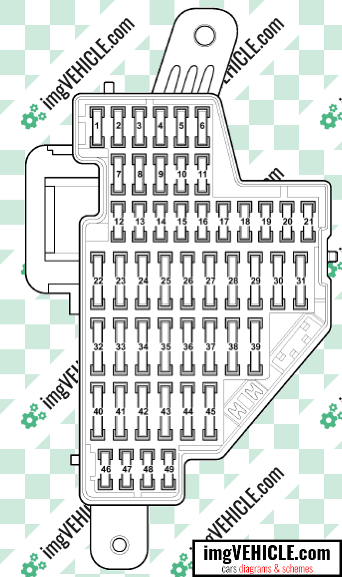
Fuse Arrangements Electronics Box Low, from May 2006
| Number | Amps | Description |
|---|---|---|
| F1 | 10A | 16-pin connector Diagnostic connection Fuel pump control module Engine Control Module (ECM) |
| F2 | 5A | ASR switch ASR/ESP button Brake pedal position sensor ABS Control Module |
| F3 | 10A | Airbag Control Module |
| F4 | 5A | Tire pressure monitoring button Garage door opener control head High pressure sensor Oil level thermal sensor Heated driver seat control module Heated frontpassenger seat control module Climatronic Control Module |
| F5 | 5A | Headlamp range control adjuster Headlamp Range/Cornering Lamp Control Module Left headlamp beam adjustment motor Right headlamp beam adjustment motor |
| F6 | 5A | Instrument Cluster Control Module Power Steering Control Module Data Bus On Board Diagnostic Interface Selector lever sensor system control module |
| F7 | 5A | Cell phone operating electronics control module Automatic dimming interior rearview mirror |
| F8 | 5A | Towing recognition control module |
| F9 | - | Not used |
| F10 | 7.5A | Garage door opener control module |
| F11 | 10A | Right headlamp power output stage |
| F12 | 10A | Driver's Door Control Module Front Passenger's Door Control Module |
| F13 | 10A | Light Switch 16-pin connector Diagnostic connection |
| F14 | - | Not used |
| F15 | 7.5A | Vehicle Electrical System Control Module |
| F16 | 10A | Heater/heat output switch Climatronic Control Module A/C Control Module Auxiliary engine coolant heater radio frequencyreceiver |
| F17 | 5A | Compass magnetic field sensor Rain/light recognition sensor Antenna selection control module |
| F18 | 5A | Parking Aid Control Module Selector lever sensor system control module |
| F19 | 7.5A | Door closing assist control module |
| F20 | - | Not used |
| F21 | - | Not used |
| F22 | 40A | Fresh air blower |
| F23 | 30A | Driver's Door Control Module Front Passenger's Door Control Module |
| F24 | 15A | Cigarette lighter |
| F25 | 25 | Rear window defogger A/C Control Module Heater/heat output switch Fresh air blower series resistor with fuse |
| F26 | 20A | Power socket 12 V (luggage compartment) |
| F27 | 15A | Fuel pump control module Transfer fuel pump Fuel pump relay |
| F28 | - | Not used |
| F29 | 10A | Mass airflow sensor Engine Control Module (ECM) (BVY) |
| F30 | 10A | Cylinder 1 fuel injector (BLF) Cylinder 2 fuel injector (BLF) Cylinder 3 fuel injector (BLF) Cylinder 4 fuel injector (BLF) |
| F31 | 20A | Brake system vacuum pump |
| F32 | 30A | Left Rear Door Control Module Right Rear Door Control Module |
| F33 | - | Not used |
| F34 | 15A | Driver seat lumbar support adjustment switch Airbag energy reserve |
| F35 | 5a | Interior monitoring sensor Interior monitoring transceiver module 2 Vehicle inclination sensor Alarm Horn Horn relay |
| F36 | 20A | Headlamp Washer Relay Headlamp washer pump |
| F37 | 30A | Heated driver seat control module Heated front passenger seat control module |
| F38 | 10A | Left headlamp power output stage |
| F39 | - | Not used |
| F40 | 40A | A/C Control Module Auxiliary heater operation relay |
| F41 | - | Not used |
| F42 | 15A | Dual washer pump relay1 |
| F43 | 15A | Towing recognition control module |
| F44 | 15A | Towing recognition control module |
| F45 | 15A | Towing recognition control module |
| F46 | 5A | Climatronic Control Module A/C Control Module Left washer nozzle heater Right washer nozzle heater |
| F47 | 5A | Auxiliary heater operation relay |
| F48 | - | Not used |
| F49 | 5A | Light Switch |
All Volkswagen EOS info & diagrams provided on this site are provided for general information purpose only. Actual Volkswagen EOS (2006-2015) diagrams & schemes (fuse box diagrams & layouts, location diagrams, wiring diagrams etc.) may vary depend on the model version.
~Jon 26-09-2018
Is the diagram correct for EOS 2014?
~Jack Johnson 06-03-2021
Where is the fuse for the sunroof motor?
~Miroslaw 09-04-2021
Where is the fuse for the sunroof motor?
~update 23-07-2021
The fuse for the sunroof motor is F33
~bikerbill 21-09-2021
where is rear assist buzzer H07 on a 2012 VW EOS
~Mel 01-10-2021
Where is the fuse for air/heater fan for EOS 2009?
~Derrol p 19-10-2021
my trunk will not open left side actuator is there a fuse help
Add comment
Posted by: celestecelestekressee0272027.blogspot.com
Source: https://imgvehicle.com/volkswagen/eos/fuse-box
Post a Comment for "2010 Mustang Fuse Box Diagram"